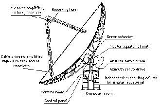
Schematic diagram of the Parkes Telescope. Note the telescope's 30 degree horizon.
The Parkes telescope is a parabolic, prime focus dish antenna with a diameter of 64 metres. When commissioned in 1961, it utilised many innovative design features that have allowed it to remain at the forefront of radio astronomy. The design was so successful that it became the model for the large antennas of NASA's Deep Space Tracking Network. These antennas, which were initially also 64 metres in diameter, are located at Goldstone in California, Madrid in Spain, and at Tidbinbilla near Canberra. The Goldstone antenna was known as the 'Mars dish', since it was to be used to track the Mariner 6 and 7 spacecraft as they flew by the planet Mars, shortly after the Apollo 11 mission, in August 1969. Bill Merrick, a JPL antenna engineer and collaborator of John Bolton's, spent many months at Parkes in the early 1960s testing the antenna structure.
The Parkes telescope is an astronomical instrument, and is designed to track radio sources across the sky at a sidereal rate. Its maximum rates of motion in azimuth and elevation are 25o/min. and 10o/min. respectively. This is far too slow to track low Earth orbit satellites, but is ideal for tracking deep space objects moving at near sidereal rates, such as Apollo 11.
 Schematic diagram of the Parkes Telescope. Note the telescope's 30 degree horizon. |
The focus cabin of the telescope contained a turn-table device with five holes in it. This was known as the feed rotator. The hole at the centre was at the focus of the telescope and was used to support the main observing receiver. The other four holes were arranged around the central hole, 90( apart. They could support other receivers which would have been offset a short distance from the focus. However, the attenuation of the signals at these off-axis positions would have been just a few decibels (~ 3 dB) down from the focus position - a useable signal was obtainable at these points. As its name suggested the feed rotator could be rotated, which was very useful since the telescope was an altazimuth mounted instrument and thus suffered from field rotation, that is, its field-of-view would appear to rotate as it tracked objects across the sky. By turning the feed rotator, the field-of-view of the on-focus receiver could be kept constant and thus polarimetry experiments conducted. A by-product of this technique was that as the feed rotator was turned, the field-of-view of the off-axis receivers would appear to move about the field-of-view, or beam, of the central, on focus, receiver along a circular arc opposite to the receivers. It was thus possible to move the telescope, and turn the feed rotator, in order to track objects with the off-axis receivers.
On 21 July 1969, the Parkes telescope had two receivers installed - one at the focus and another, less sensitive receiver, in one of the four off-axis positions. The precise offset position of the off-axis receiver has not been recorded, but according to Bruce Thomas there were two possible positions: one gave a field-of-view 1.2o from the main beam, and the other gave a field-of-view 1.43o from the main beam.