Interference Monitoring System (IMS)
The Interference Monitoring System (IMS) has precipitated out of a requirement to measure weak interference signals, which may affect the operations of the radiotelescope. The receiver systems used on the radiotelescope, are very sensitive, and main-beam side-lobe coupling of off-site licensed and sometimes unlicensed transmitters, cause RFI. Existing techniques for measuring RFI typically utilize an antenna, a set of low-noise amplifiers, and a spectrum analyzer. With this setup, the typical noise floor of the measurement system, is sometimes many orders of magnitude greater than the interference power level, and thus, the interference signal is buried in the measurement system noise floor. This can sometimes be overcome by reducing the resolution bandwidth on the measuring spectrum analyzer, but this can be restrictive, in terms of sweep times across the RF spectrum, and thus, the setup yields a measurement system incapable of providing useful and timely results.
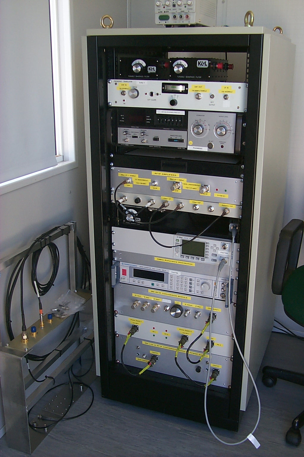
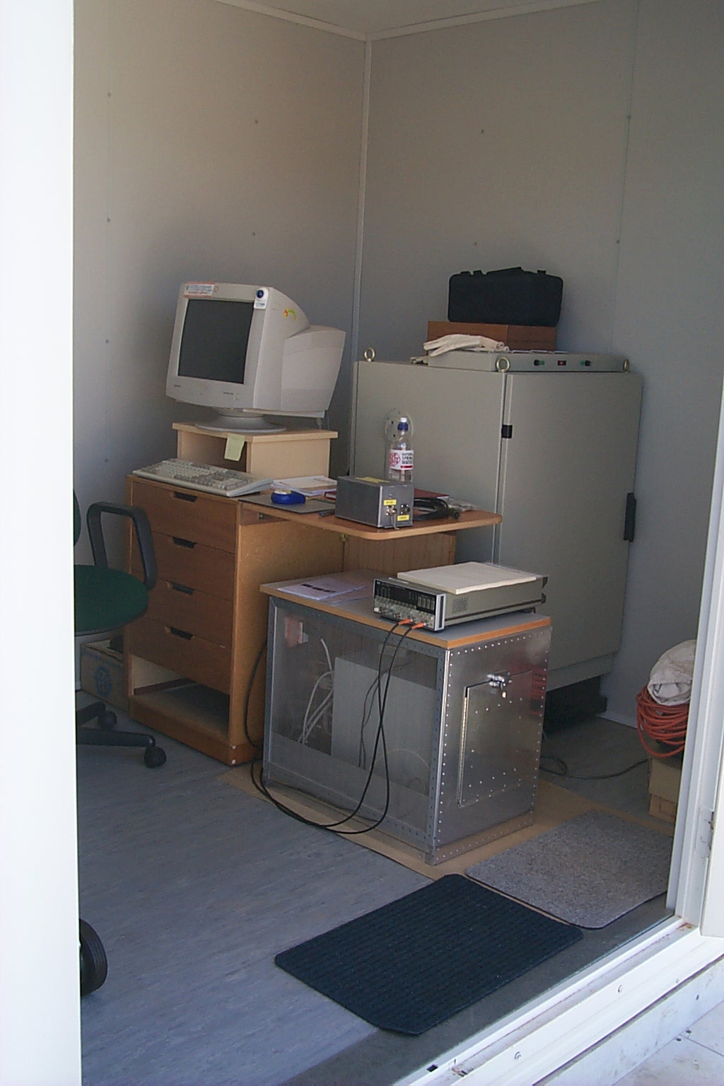
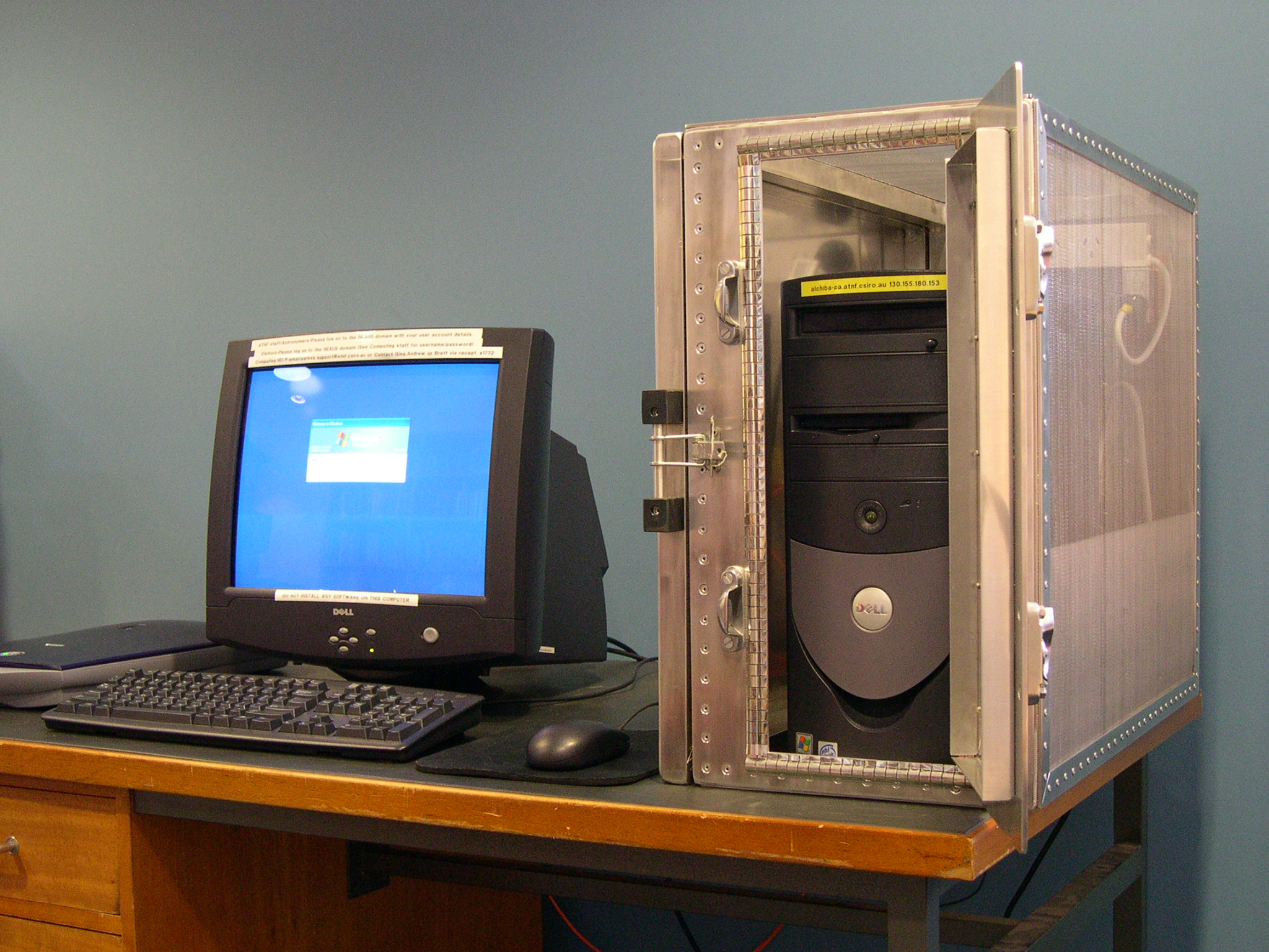
The IMS moves away from the measurement principles of the spectrum analyzer, which utilizes a swept narrow-band filter across the spectrum, by utilizing the principles of noise measuring radiometers. Radiometers afford the ability to measure the extremely weak signals, through the use of integration techniques, resultant from a sampler/correlator backend system. The IMS is composed of a number of modules, all of which constitute a mini-radiotelescope, in operation. There are antennas, low-noise amplifiers, an RF/IF down-conversion system, and a sampler/correlator system. In addition, to provide an interface to the correlator control computer, a regular desktop PC is used, housed in a purpose built and designed PC RFI cage. In order to minimize RFI emissions from the backend digital hardware, namely the correlator control computer, the sampler/correlator, and the sampler clock, all of the equipment is housed in a commercially screened rack.
The RF/IF down-conversion system provides conversion for an RF input range of 400-3500MHz, and outputs an IF, centred at 160MHz, bandwidth limited to 64MHz, for direct input into the sampler/correlator. Out-of-band spurious signals, and image rejection filtering is provided before the RF/IF down-conversion, through the use of a number of tunable bandpass filters. The IMS sampler/correlator is a modified Multibeam receiver sampler/correlator, allowing for the production of either single channel 1024 autocorrelation, or 2048 autocorrelation products. The sampler is a 2 bit, '3 level', at 128MSamples/sec, over an IF bandwidth of 64MHz. For the typical configuration used, with 1024 channels, over 64MHz bandwidth, a frequency resolution of 62.5kHz results, which is adequate for most applications.
Example spectra from the IMS can be found at:
 Analogue TV Signal WIN CH33 analogue TV signal from Mt Canobolas
Digital TV Signal ABC CH36 digital TV signal from Mt Canobolas
DME Signal at L-Band Parkes Airport Distance Measuring Equipment Beacon. Expanded view is here DME Beacon zoom view
DRCS Signal at L-Band Digital Radio Concentrator Service. Expanded view is here DRCS zoom view
HIPASS observing band Spectrum used for HIPASS/ZOA survey
OH observing band with RFI Part of the OH observing band with RFI, view from the north. Possible source is Globalstar uplink facility at Dubbo. Expanded view is here OH observing band zoom